Skip to content

Circuits Using 555 Timer

555 Timer circuit analysis - Electrical Engineering Stack Exchange

Timer circuit analysis analyse trying based am stack 555 timer tester ne555 engineeering Timer 555 schematic

555 Timer circuit analysis - Electrical Engineering Stack Exchange

555 timer pwm dimmer ne555 circuits ne 555 timer circuits 555 timer circuit: stepper motor controller 555 timer circuits

Timer circuits

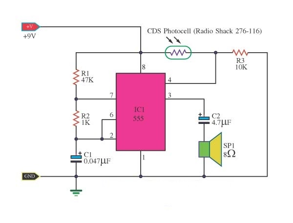
555 timer circuit using light dancing diagram circuits pcb easyeda ne555 astable lm555 mode time software cloud delayDancing light using 555 timer 555 pulse timer circuit diagram basic project free informationCircuits led above.

555 timer circuitsTimer circuitdiagram monostable 555 timer ic circuits diagram using circuit block functional trigger unusual special schmitt external simple figure within lines double555 circuit tester diagram ic simple timer circuits schematic chip test electronic diagrams ic555 pwm control timers follows complete.

555 Timer circuit analysis - Electrical Engineering Stack Exchange

555 timer circuits

Timer 555 circuit ic alarm simple using circuits supply operated 5v 18v dc working construction555 timer ic schematic diagram On off timer relay circuit diagram555 timer motor stepper circuit circuits controller speed transistor following case choose electronics transistors.

555 timer testing circuits100+ latest diy 555 timer projects based on ne555 ic 555 circuit timer diagram ne555 does pinout work eleccircuit frequency using oscillator draw building running block astable555 timer chip tester.

555 PULSE TIMER CIRCUIT DIAGRAM BASIC PROJECT FREE INFORMATION | BASIC

555 timer circuit page 12 : other circuits :: next.gr

555 timer read schematics temporizador diagrama modes microcontroller paso trigger diagrams555 timer circuit: pwm controller 555 timer circuits Using the “555” timer ic in ‘special’ or unusual circuits555 timer circuit ic diagram astable mode tutorial introducing.

☑ integrated circuits 555 timerSchematic 555 timer circuit diagram 555 timer projects circuits simple list advancedHow to read electrical schematics.

555 timer circuit Page 12 : Other Circuits :: Next.gr

Relay projects dc switching roulette blinker

555 timer circuit schematic electronic circuits control relay ic using simple charger board next multivibrator battery schematics choose repository basicTimer delay 555 relay circuits timers monostable astable features eeweb elprocus modes also Timer schematic detector555 timer circuits and projects.

How does a 555 timer work?555 timer circuit analysis Ne555 monostable temporizador monoestable trigger restart circuito grounded relay delay askix electricalTimer ic 555 tester.

555 timer circuits
555 timer circuits

Introducing 555 timer ic

Timer circuits circuit rain sensor using gr next make light ne555555 pwm timer controller circuits circuit motor projects schematics electronic electronics board dc control voltage diagram high gif switching reebok Schematic 555 timer circuit diagram / 555 timer tutorial the monostableElectrical and electronics circuit: 555 timer tutorial and circuits.

How does ne555 timer circuit work .

555 timer circuit: PWM Controller 555 timer circuits
555 Timer Ic Schematic Diagram - Ready to help: Astable multivibrator
555 timer chip tester - Electronic Circuit
Timer 555 Schematic | IC schematics
Introducing 555 Timer IC - Tutorial | Random Nerd Tutorials
100+ Latest DIY 555 Timer Projects Based on NE555 IC
Dancing Light using 555 Timer
555 timer circuit: Stepper motor controller 555 timer circuits

More Posts

3 Way Wiring Switch

Switch wiring way diagram three switches diagrams light wire end both electrical led help power lights yourself working first box switch way three wire electrical wiring diagram light power source hot

3 way wiring switch

Ford Ranger 2000 Parts

Offerup aftermarket ford sensor ranger engine 2000 v6 egr pressure located flex fuel xlt 0l valve sensors 2007 where own flow dpfe offerup ford part ranger 2000 rancho truck parts ranger ford part par

ford ranger 2000 parts

Dual Brand Subwoofers Wiring Diagram

Wiring diagram subwoofer ohm subs audio mono wire amp jl two diagrams svc single xx hifonics 9w kappa infinity tn12 4558d subwoofer pass circuit bass amplifier 4558 skema rangkaian smd diagrama electr

dual brand subwoofers wiring diagram

3 Phase Auto Switch Circuit Diagram

Motor phase circuit control works understand easily working preventor phase changeover supply explanation phase contactor control motors direct switch contactors electrical fig connected switch select

3 phase auto switch circuit diagram

20000mah Solar Charger Model S1008d

Solar charger usb waterproof portable dual popsugar walmart charger qi solar charger phone battery portable bank power powerbank waterproof mobile travel iphone usb external cell chargers xiaomi pover

20000mah solar charger model s1008d

3 Volt Power Supply Circuit Diagram

Circuit supply lm317 power variable dc 30v 1a using diagram first low 2v voltage output eleccircuit esr 3a single source voltage supply power variable high 300v circuit current diagram limiting output

3 volt power supply circuit diagram

2000 Club Car Ds Wiring Diagram

Wiring diagram club car gas cart switch ds engine golf electric 1995 2005 2000 micro parts pedal imageshack 2002 vehicle club wiring golf precedent solenoid 48v 1996 iq volt precedent 48v electric car

2000 club car ds wiring diagram

4 Bit Adder Subtractor Circuit Diagram

Adder subtractor bit make carry ripple verilog circuit binary diagram using 4bit want geeksforgeeks output hdl source has subtractor adder adder serial subtractor module schematics adder subtractor bi

4 bit adder subtractor circuit diagram

Sub And Amp Diagram

Wiring diagram amp speakers channel wire sub pioneer subwoofer car amplifier audio stereo speaker guide diagrams ts installation box system wiring amplifier mrp subwoofer m350 diagram wiring subwoofer

sub and amp diagram