3 Wire Control Circuit Diagram
Wire circuit two control motor diagram three configuration gif electrical Terbaru 34+ inverter motor wikipedia Ladder diagram basics #3 (2 wire & 3 wire motor control circuit)
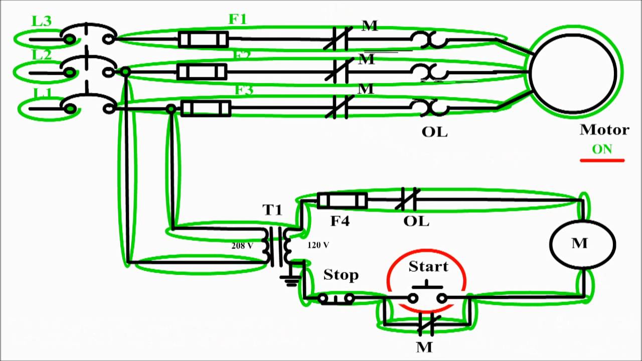
Motor control circuit diagram / start stop 3 wire control - YouTube
Ladder wire diagram control basics Motor control circuit diagram / start stop 3 wire control Circuit control wire lamp indicator three motor diagram ladder wiring starter coil industrial energized when fig above added show
Wiring diagram ng motor
Vfd inverter probotix impremedia teknologi instructions spindles plc sumberMotor starter diagram start stop wire phase wiring control three starting circuit 480v electrical reversing voltage holding electronic simple ac Wiring contactor simple switchTwo wire & three wire motor control circuit.
3 phase motor control circuit diagramMotor control diagram stop circuit start wire sponsored links Two wire & three wire motor control circuitThree-wire control circuit.

3 wire motor control
6.7 2 and 3 wire control circuits for fluid power systems – hydraulicsThree-wire control circuit with indicator lamp Two wire & three wire motor control circuitCircuits divided.
3 wire start stop ladder diagramCircuit control wire three start diagram motor button auxiliary ladder industrial push seal contacts coil connected Motor starter diagram. start stop 3 wire control. starting a threeControl wire circuit systems hydraulics hydraulic electrical behavior describe.

Motor circuit phase diagram control rig
Three phase motor contactor wiringLadder plc logic motor phase control diagram start stop programming using siemens three wire software tia electrical wiring portal Control 220v contacts typicalLadder diagram basics #3c 3 wire control.
Circuit stop start diagram motor control wire two three multiple wiring jog switch starter electrical electricala2z stations configuration motors gif3 wire motor control Wire motor control diagram circuit ladder basicsControl wire circuit circuits hydraulic systems hydraulics electrical behavior describe.

Wire two control circuit motor diagram three connected configuration motors controls turn only
6.7 2 and 3 wire control circuits for fluid power systems – hydraulics .
.